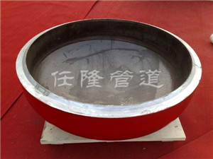
Hemispherical head HH
In a head factory, hemispherical heads are generally formed by hot pressing or cold pressing with molds, depending on different thicknesses and materials.
Cylinder forming process: Manufacturing process
Select materials and their grades, conduct chemical composition inspection of the materials, and after the mechanical properties are qualified, straighten the steel plates. Methods include manual straightening, mechanical straightening and flame straightening.
Material preparation − calculate the developed area according to the drawing − marking out − cutting − edge processing − forming (head bending, plate rolling) − assembly − welding − welding quality inspection − assembly welding − quality inspection.
Head manufacturing process: Manufacturing process
Select materials and their grades, conduct chemical composition inspection of the materials, and after the mechanical properties are qualified, straighten the steel plates. Methods include manual straightening, mechanical straightening and flame straightening.
Material preparation − calculate the developed area according to the drawing − marking out − cutting − edge processing − forming (flame heating for large heads − flanging piece by piece on a hydraulic press − one-step forming for small heads) − assembly − welding − welding quality inspection − assembly welding − quality inspection.
Regarding the reliability of the connection zone between the cylinder and the head of a high-pressure vessel, hemispherical heads are generally adopted for large-diameter high-pressure vessels because they have a favorable stress state under internal pressure and require a smaller thickness. Since the thickness of a hemispherical head differs greatly from that of the connected cylinder, a transition zone inevitably exists, and a conical transition section is usually used for connection. Therefore, the transition zone becomes one of the high-stress zones of high-pressure vessels.
Discontinuous zones of pressure vessels are often high-stress zones. Due to the generally complex geometric shapes of discontinuous zones, it is difficult to conduct an exhaustive solution by analytical methods, so the finite element method is usually adopted for calculation. Structural discontinuities of pressure vessels are divided into two categories, namely overall structural discontinuity and local structural discontinuity. Overall structural discontinuity refers to a source of stress or strain that affects a considerable part of the structure, i.e., discontinuity in the geometry, material or load of the vessel. Structural discontinuity causes additional edge stresses, thereby affecting a considerable part of the structure. Examples include the connection zone between the head and the shell, the connection zone between the flange and the shell, the nozzle zone, and joints of different diameters, thicknesses or materials. Local structural discontinuity refers to a source of stress or strain that affects a relatively small range of the structure. Examples include small fillet radii, small connectors, partial penetration welds or small holes. In practice, many structures may involve both overall and local structural discontinuities. For instance, at a nozzle, there are overall structural discontinuity stresses caused by inconsistent free deformation between the nozzle and the shell under pressure loading and during deformation coordination, as well as local structural discontinuity stresses induced by local weld dimensions such as transition fillets. The total stress of the structure is the combined result of the superposition of the two. Failure of pressure vessels often occurs at structural discontinuities. Therefore, research on the reliability of discontinuous regions of pressure vessels is highly necessary and has practical economic benefits.